Features of strain gauge installation
Method of installing strain gauges
It is fair to say that this method of installing strain gauges will be relevant not only for Keli load cells, but also for a number of other load cell models used in road and railroad scales of foundation and non-foundation type.
For quick installation of strain gauges, embedding units are required. At the first stage, the upper base plate is welded to the calculated location of the loading platform. The upper bowl for the load cells is attached to the base plate. The most reliable, fastest, and most technologically advanced method of installation is to use socket head screws.
The lower base plate is fixed by welding. It is fixed to the foundation slab by manual open-circuit electric arc welding. When installing strain gauges, the base plate must have dimensions of at least 23x23 cm with a thickness of 2 cm.
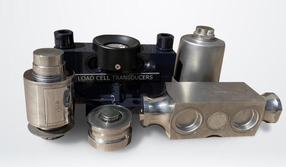
The strain gauges are directly fixed to the lower base plate using spring washers, 16/30 bolts, and eccentrics. Keli strain gauges have a spherical bearing surface that must be fully seated in the socket located on the upper bowl.
After installing the strain gauges, the eccentrics are used to adjust the position of the lower bowl on the plate. The strain gauge should be placed vertically. After the strain gauges are installed, fix the grounding shunt to the upper and lower base plates.
Principles of installation of strain gauge weight sensor
The basic principles of installation of strain gauges are the same, regardless of the version. It is enough to have an idea of such a concept as the signal of the measuring bridge.
The Whitston bridge in strain gauge installation diagrams is denoted by a rhombus, each side of which is called an "arm" and the corners are called nodes. In the classical version, the bridge includes three functional components: resistors, a strain gauge voltage source, and a recording circuit. In the case of strain gauges, other variants are possible, in particular, "half bridge" and "quarter bridge". The strain gauges can be connected to the arms either in parallel or in series.
The main purpose of the Whitston bridge is to convert small changes in resistance that occur in the strain gauge into voltage output signals. Let's take a small example of a strain gauge: when a strain of 1000 μm/m occurs, a 100-ohm resistor installed in the strain gauge changes resistance by only 0.2 ohms. The absence of a bridge will not allow even small changes to be registered.
Situations where you need to connect several load cells arise quite often. Let's consider the specifics of connecting load cells using the example of a tank with three supports and 350 Ohm load cells.
In this case, the strain gauges are connected in parallel, subject to several conditions. All load cells used must have the same sensitivity and sufficient current.
If the load cells are connected in parallel, the resistance will be 117 ohms. Provided that the load cell power supply has a voltage of 10 V, the current will be approximately 85 mA. The peculiarity of the parallel connection of load cells is that it summarizes the total load and preserves the output signal. If each strain gauge weight sensor has a measuring range of 200 N, then the figure is tripled when the above scheme is implemented.
Installation recommendations for Keli strain gauges

- When installing Keli strain gauges, no impact is allowed.
- All welding work performed during the installation of Keli load cells must be completed before mounting. The inrush current of the arc discharge can damage the load cell.
- All surfaces involved in the installation of Keli load cells must be absolutely flat and leveled using a spirit level.
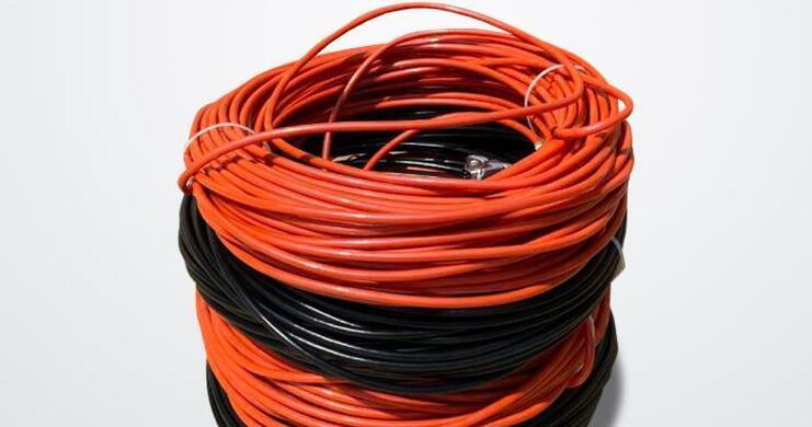
- Note that all load cell cables must be routed separately from the power cables.
- If necessary, silicone may be used to further seal the junction box of the Keli load cells.
- If Keli load cells are to be operated in unstable weather conditions, use metal covers to protect the load cell from wind, sun and heat.
Keli strain gauges can be directly connected to the balance via a 4-wire shielded or 6-wire cable. The choice of this or that option depends on the model of the Keli load cell.